Based on ASME Code :-
1. Expanded or rolled and flared.
2. Flared not less than 1/8 in, rolled and beaded
3. Flared, rolled and welded.
4. Rolled and seal-welded, provided the throat of the seal weld is not more than 3/8 in and the tube rerolled after welding.
5. Superheater, reheater, waterwall or economizer tubes may be welded without rolling or flaring, provided the welds are heat-treated after welding and the welding is done according to Code requirements.


Internal
1. Waterlines. Tubes. Due to oxygen and organic materials during boiling process.
2. Vicinity of boiler water dicharge resulting in oxygen release.
3. Top of lower tube sheet because of scale formation.
4. On and arround of stay bolts as a result of stresses imposed and the subsequent expansion and contraction (stress corrosion).
5. In water legs especially at the bottom - pitting scale.
External
1. Top of tube sheet, bottom tube sheet and tube ends. Acid formed.
2. Arround manhole, handhole and washout openings. Due to leakage and thermal expansion.
3. At the bottom shell, water legs and furnade sheet as a result of soot attack.
4. Arround all openings including valve, steam connection, feedwater connection, blowdown, water column and leakage.
1. The internal furnace wall subject to compressive forces.
2. Small furnaces diameter and short length may be self-supporting if the wall thickness is adequate.
3. For larger furnaces, one of four methods of support may be used as below :
3.1 Corrugating the furnace walls
3.2 Dividing the furnace length into sections with as stiffening rings (Adamson ring) between section
3.3 Using welding stiffening rings
3.4 Installing stay bolts between furnace and the outer shell.


Din Msiea
1. Tolonglah dalam kebajikan. Nescaya ia membawa kebaikan dunia dan akhirat.
2. Din adalah senior saya di MRSM KT 94/95. Kami ditemukan semula pada tahun 2006 semasa menduduki peperiksaan Jurutera Stim Gred 2. Dua tiga malam sebelum peperiksaan, di Megah D'Haru Hotel sebelah bangunan Perkeso KK, kami akan buat study group bersama - sama Rosliezan Md Husain dan rakan - rakan yang lain. Brainstoming. Knowledge transfer from brain to brain. Tak lupa juga banyak handbook kena share dari pen drive ke pendrive.
3. Itulah cara kami belajar nak lulus periksa lebih 10 tahun lepas.
4. Din ada daya momentum keinginan yang kuat dalam industri boiler. Tanpa henti hingga kini.
5. Dari inisiatif beliau, MSIEA kini dikenali semua pemain industri.
6. Saya doakan beliau sentiasa dicucuri rahmat Allah selamanya. Semoga segala usaha beliau dipermudahkan.
7. Teruskan usaha murnimu. Kami akan sentiasa menyokong.
*ini adalah gambar terbaru May 2017 kami berjumpa sejak kali terakhir 2007.
#tributetodinmsiea


1. Available fuel.
2. Capacity and pressure required.
3. Space conditions in the building.
4. Cost. But first cost may be high but it may compensate by lower operating and maintenance expences.
5. Individual preference.

1. Pressure at 3206.2 psi / 221 bar.
2. At this pressure steam & water at the same density - steam is compressed as tightly as the water.
3. When this mixture is heated 705.4 degree F / 374 degree C, superheated steam is produced to do useful high - pressure work.
4. Example to run turbine - generators.
LIST OF SECTIONS
ASME BPVC Section I - Rules for Construction of Power Boilers
ASME BPVC Section II - Materials
Part A - Ferrous Material Specifications
Part B - Nonferrous Material Specifications
Part C - Specifications for Welding Rods, Electrodes and Filler Metals
Part D - Properties (Customary)
Part D - Properties (Metric)
ASME BPVC Section III - Rules for Construction of Nuclear Facility Components
Subsection NCA - General Requirements for Division 1 and Division 2
Division 1
Subsection NB - Class 1 Components
Subsection NC - Class 2 Components
Subsection ND - Class 3 Components
Subsection NE - Class MC Components
Subsection NF - Supports
Subsection NG - Core Support Structures
Subsection NH - Class 1 Components in Elevated Temperature Service
Appendices
Division 2 - Code for Concrete Containments
Division 3 - Containments for Transportation and Storage of Spent Nuclear Fuel and High Level Radioactive Material and Waste
Subsection WA - General Requirements for Division 3
Subsection WB - Class TP (Type B) Containment
Subsection WC - Class SC storage Containments
Division 4 - Reserved for fusion reactors (Not Active)
Division 5 - Construction rules for high temperature reactors (Not Active)
Subsection HA - General Requirements
Subsection HB - Class A Metallic Pressure Boundary Components
Subsection HC - Class B Metallic Pressure Boundary Components
Subsection HF - Class A and B Metallic Supports
Subsection HG - Class A Metallic Core Support Structures
Subsection HH - Class A Non-Metallic Core Support Structures
ASME BPVC Section IV - Rules for Construction of Heating Boilers
ASME BPVC Section V - Nondestructive Examination
ASME BPVC Section VI - Recommended Rules for the Care and Operation of Heating Boilers
ASME BPVC Section VII - Recommended Guidelines for the Care of Power Boilers
ASME BPVC Section VIII - Rules for Construction of Pressure Vessels
Division 1
Division 2 - Alternative Rules
Division 3 - Alternative Rules for Construction of High Pressure Vessels
ASME BPVC Section IX - Welding and Brazing Qualifications
ASME BPVC Section X - Fiber-Reinforced Plastic Pressure Vessels
ASME BPVC Section XI - Rules for Inservice Inspection of Nuclear Power Plant Components
ASME BPVC Section XII - Rules for the Construction & Continued Service of Transport Tanks
Source WIKIPEDIA
ASME Boiler and Pressure Vessel Code
The ASME Boiler & Pressure Vessel Code (BPVC) is an American Society of Mechanical Engineers (ASME) standard that regulates the design and construction of boilers and pressure vessels.[1] The document is written and maintained by volunteers chosen for their technical expertise .[2] The American Society of Mechanical Engineers works as an Accreditation Body and entitles independent third parties such as verification, testing and certification agencies to inspect and ensure compliance to the BPVC.[3]
History
The BPVC was created in response to public outcry after several serious explosions in the state of Massachusetts. A fire-tube boiler exploded at the Grover Shoe Factory in Brockton, Massachusetts on March 20, 1905 which resulted in the deaths of 58 people and injured 150. Then on December 6, 1906 a boiler in the factory of the P.J. Harney Shoe Company exploded in Lynn, Massachusetts. As a result, the state of Massachusetts enacted the first legal code based on ASME's rules for the construction of steam boilers in 1907.[4][5]
ASME convened the Board of Boiler Rules before it became the ASME Boiler Code Committee which was formed in 1911. This committee put in the form work for the first edition of the ASME Boiler Code - Rules for the Construction of Stationary Boilers and for the Allowable Working Pressures, which was issued in 1914 and published in 1915.[5]
The first edition of the Boiler and Pressure Vessel Code, known as the 1914 edition, was a single 114-page volume.[6][7] It developed over time into the ASME Boiler and Pressure Vessel code, which today has over 92,000 copies in use, in over 100 countries around the world.[5] As of March 2011 the document consisted of 16,000 pages in 28 volumes.[7]
After the first edition of the Code, the verifications that the manufacture was to the Code was performed by independent inspectors, which resulted in a wide range of interpretations. Hence in February 1919, the National Board of Boiler and Pressure Vessel Inspectors was formed.[5]
ASME BPVC TIMELINE[5][8]
Year Activity
1880 The American Society of Mechanical Engineers is founded
1884 First performance test code: Code for the Conduct of Trials of Steam Boilers
1900 First revision of an ASME standard, Standard Method of Conducting Steam Boiler Tests
1911 Establishment of a committee to propose a Boiler Code
1913 New Committee to revise the Boiler Code
1914 Issuance of the first Boiler Code
1915 Standards for Specifications and Construction of Boilers and Other Containing Vessels in Which High Pressure is Contained
1919 National Board of Boiler and Pressure Vessel Inspectors formed
1924 Code for Unfired Pressure Vessels
1930 Test Code of Complete Steam-Electric Power Plants
1956 Committee established for ASME Pressure Vessel Code for Nuclear Age
1963 Section III (Nuclear Power) of ASME Boiler and Pressure Vessel Code
1968 ASME Nuclear Power Certificate of Authorization Program commences
1972 ASME expands its certification program worldwide; first ASME manufacturer certification issued outside of North America
1978 First ASME publication of Boiler and Pressure Vessel Committee interpretations
1983 ASME Boiler and Pressure Vessel Code published in both conventional and metric units
1989 Boiler and Pressure Vessel Code published on CD-ROM
1992 First Authorized Inspection Agency accredited
1996 Risk technology introduced into the Boiler and Pressure Vessel Code
1997 High Pressure Vessel Code
2000 C&S Connect (on-line balloting and tracking system) launched for Boiler and_Pressure Vessel Committees
2007 ISO TC11 Standard 16528—Boilers and Pressure Vessels published, establishing performance requirements for the construction of boilers and pressure vessels and facilitating registration of BPV Codes to this standard
2008 Polyethylene plastic pipe introduced into the Boiler and Pressure Vessel Code, Section III
2009 ASME Boiler and Pressure Vessel Committee reorganized from one consensus body to ten consensus bodies
Source WIKIPEDIA
Boiler
A closed pressure vessel in which a fluid is heated for use of external to itself by direct application of heat resulting from the combustion of fuel (solid, liquid or gaseous) or by electricity or nuclear energy.
Steam Boiler
A closed vessel
In which steam is generated or other vapour is generated
For use of external to itself by
Direct application of heat resulting from combustion of fuel (solid, liquid or gaseous) or by electricity or nuclear energy.
Steam or vapor boiler operating above 15 psig and exceeding the miniature boiler size.
1. Installing non - code SV with no pressure or capacity stamping on the valve.
2. SV do not matcb pressure rating and capacity of the boiler.
3. The relief valve installed in the wrong place.
4. Undersize inlet and outlet.
5. Outlet piping not sufficiently braced against reaction forces. Lead to flanged connections breaking.
1. To ensure the flow of gases.
2. Natural and mechanical draft.
3. Without draft, stagnant in the burning process would result in the combustion die from lack of air.
1. Sulfur burns to sulfur dioxide.
2. When mixed with water or water vapor, forms sulfurous acid which is corrosive to tubes, breechings and economizer section.
3. To monitor the furnace temperature to reduce the effects.

1. Primary air : air mixed with fuel at or in the burner.
1/3
2. Seconday air : air brought through burner or opening in furnace wall or floor to complete the combustion in the furnace.
2/3 for oil type boiler.

Ash and slag are impurities that does not burn to a gas.
The solid particles at high velocity are carried through the boiler with gas in suspension..
Or flyash.
Flyash can be very abrasive to the the tube sections.

Some carbon associated in hydrocarbon compounss breaks away as free carbon.
Thus we always have problem to burn carbon particles if we do not have ample time to pass through the furnace.
Incomplete combustion of carbon is the germ of smoke and soot.
If the furnace is small and boiler tubes @ heating surface are badly located, carbon can not possibly burn to completion.
The steps of
1. Bringing air and fuel together
2. Raising the mixture to ignition temperature
3. Sweeping away successive layers of gas from fuel particles
4. Burning carbon as far as possible
5. Occur while the fuel and air travel from burner to furnace outlet.
But at short time, to achive complete combustion is depends on
1. Distance traveled
2. The speed
3. Flow is turbulent or not.


Tube or pipe for circulating of water from the water space of the steam drum to waterwall headers.
The downcomer is always placed outside the boiler casing so that it does not not absorb heat from the furnace or boiler.
It must not disturb the natural gravity circulation of the cooler water downward which might occur if it absorbed heat.

1. To cool and protect the furnace lining.
2. Depend on the type of boiler, waterwall tube may be 10% of boiler's heating surface, yet represent 50% of the total heat absorption.
3. Absorb heat from the furnace to increase the unit's generating capacity.
4. Make the furnace air tight (on pressurized furnaces with tangent welded tubes).

1. According to ASME Code, the heating surface is calculated from the side exposed to the products of combustion.
2. Thus, the outer diameter is larger than inner diameter.

1. Safer
2. Accessible for cleaning, inspection and repairs.
3. Fasters steamers due to large heating surface, long gas travel and rapid & positive water circulation.
4. Greater overloads and respond more readily to sudden changes and fluctuations in demand.
5. Drum not exposed to radiant heat of the fire.
6. The biggest advantage : freedom to increase the capacities and pressures.

Charpy impact test
The Charpy impact test, also known as the Charpy V-notch test, is a standardized high strain-rate test which determines the amount of energy absorbed by a material during fracture. This absorbed energy is a measure of a given material's notch toughness and acts as a tool to study temperature-dependent ductile-brittle transition. It is widely applied in industry, since it is easy to prepare and conduct and results can be obtained quickly and cheaply. A disadvantage is that some results are only comparative.
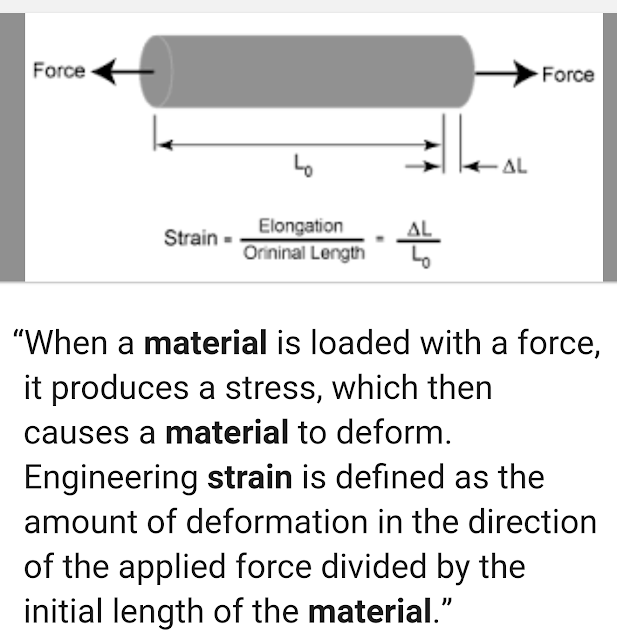
In materials science, creep (sometimes called cold flow) is the tendency of a solid material to move slowly or deform permanently under the influence of mechanical stresses. It can occur as a result of long-term exposure to high levels of stress that are still below the yield strength of the material. Creep is more severe in materials that are subjected to heat for long periods, and generally increases as they near their melting point.
The rate of deformation is a function of the material properties, exposure time, exposure temperature and the applied structural load. Depending on the magnitude of the applied stress and its duration, the deformation may become so large that a component can no longer perform its function — for example creep of a turbine blade will cause the blade to contact the casing, resulting in the failure of the blade. Creep is usually of concern to engineers and metallurgists when evaluating components that operate under high stresses or high temperatures. Creep is a deformation mechanism that may or may not constitute a failure mode. For example, moderate creep in concrete is sometimes welcomed because it relieves tensile stresses that might otherwise lead to cracking.
Unlike brittle fracture, creep deformation does not occur suddenly upon the application of stress. Instead, strain accumulates as a result of long-term stress. Therefore, creep is a "time-dependent" deformation.
Preventing creep
There are three general ways to prevent creep in metal. One way is to use higher melting temperature metals. The second way is to use materials with greater grain size. The third way is to use alloying.


Demineralization Plant
The function of demineralization plant is to remove dissolved salt by ion exchange method (chemical method) and there by producing pure feed water for boiler.
DEMINERALIZATION PLANT
The salts which make the water hard are generally-chloride,
carbonates,
bi-carbonates,
silicates and phosphates of sodium,
potassium,
iron,
calcium and
magnesium.
In D M plant there are three types of resin used for boiler feed water treatment process -
1. Cation exchange resin
2. Anion exchange resin
3. Mixed Bed resin
Resins are chemical substances (usually polymers of high molecular weight) used to react with salts and eliminates them by chemical process.
As the name suggests, the cation exchange resin, exchanges the cation and anion exchange resin, exchanges anions with the salts dissolved in hard-water.
Cation Exchange Resin
Thus H2SO4, H2CO3 are also produced.
We have removed Na+ but the water has become acidic.
Anion Exchange Resin
This way we have eliminated Cl- and thus acidity of the water.
Similar reaction for H2SO4 also. dm plant
Mixed Bed Resins
These mixed bed resins are used in Demineralization plant of boiler feed water treatment, to remove the ions (especially Na+ and SO32-) which may further present in the water after foregoing process of purification.
Degasser
The function of degasser tower is to remove carbonate ions by forming carbon-di-oxide. In degasser tower stream of water is poured from top and air is blown from bottom to top. In the pressure of air the carbonic acid (H2CO3) present in the water dissociates into H2O and CO2.
This CO2 is free to mix with air.
Benefits of using degasser are:
It removes the carbonic acid and other gases mixed with water by simple physical method and thereby reduce the chances of corrosion.
It saves the resins which are very costly chemicals and thereby improves the economy of boiler feed water treatment process.
The H2CO3 free water is now collected in degasser sump and then pumped to anion exchange resin inlet.